Performance Trends, Inc.
Producing Quality Computer Tools for Racers and Engine Builders since 1986
Wide Band UEGO A/F (lambda) Sensors
Affordable, Rugged True A/F Sensors and Controller for Accurate Engine Tuning and Troubleshooting on Dyno or In Vehicle
Our DT3-AF1 A/F sensor/controller
systems uses a Bosch 5 wire oxygen sensor to accurately measure A/F ratio, or
Lambda, over a wide range of values from approximately .6 to 1.3 Lambda. For typical
gasoline, this is from approximately 9:1 rich up to 18:1 lean. ![]() for info on our DT2-AFRM Mini Remote Sampling system for small engines and
chassis dynos.
for info on our DT2-AFRM Mini Remote Sampling system for small engines and
chassis dynos.
New (as of Dec 2015) A/F Checker
 click image to enlarge
 ![]() for info on our A/F Checker to verify the accuracy of your A/F
Measurements.
for info on our A/F Checker to verify the accuracy of your A/F
Measurements.
New (as of July 2010) Very Affordable DT3-AF1 Single A/F channel
 click image to enlarge
Our systems come with Molex connectors for plugging directly into our DataMite data loggers. For vehicle installations, the user must provide 9-18 VDC power (typically from the vehicle's battery). For dyno installations, we recommend the DT3-AF1P part number which come with AC power supplies, as shown as the option in the figure above.
Exhaust Oxygen Sensor Theory
Typical production car O2
sensors rely on "nernst cell" technology, commonly called "Narrow Band",
"2 wire", "4 wire" and sometimes erroneously described as
"Wide
Band". This is a very cost effective method that outputs a voltage based on
the oxygen content of the gas being sampled. It is accurate in the region
surrounding stoichiometric operation and leaner. Unfortunately, in the rich
region where high performance engines usually operate, their accuracy and
repeatability is virtually non-existent.
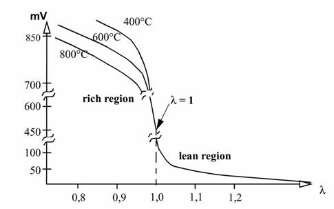
Characteristic
curve of an nernst cell type O2 Sensor
The rich region output of
a common O2 sensor is very temperature dependant, which renders it useless if an
accuracy greater than 1.5:1 AFR is desired. This is immediately obvious given
the fact that a single output voltage actually represents wildly different AFR's depending on the unregulated and unmeasured sensor temperature. These
sensors were designed for operating closed loop around the stoichiometric AFR
(14.64 for gasoline), and for performance tuning they are useless.
The heart of the
UEGO
type sensors use a "current pump" within the sensor itself to determine the
actual oxygen concentration within the sensing element or, lacking any O2, it
determines the amount of oxygen required to regain stoichiometric operation. The
output is in the form of a very small current which varies depending on the
air-fuel ratio. This is completely different from a normal oxygen sensor (1, 2
and 4 wire types) which directly output a voltage. The UEGO design allows
measurement of the exact air fuel ratio over the entire operating range.
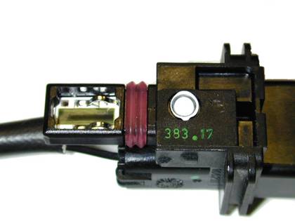
UEGO
sensors laser etched calibration resistor
A weld-in M18 X 1.5 boss is
supplied for sensor installation. Mount the O2 in the Exhaust System at least 18
inches downstream from the exhaust port as the extreme temperatures of the
exhaust can harm the sensor. The sensors internal heater will warm the sensor to
the optimum operating temperature. If available, the factory O2 sensor location
is usually preferable. On turbocharged engines the UEGO sensor must be installed
after the Turbo Charger, if not, the pressure differential will greatly effect
the accuracy of the unit. In applications with a catalytic converter, the UEGO
sensor must be mounted BEFORE the converter. In applications with an auxiliary
air pump, the UEGO sensor must be mounted BEFORE the pump input to the exhaust
stream. Installation angle should be inclined at least 10° towards horizontal
(electrical connection upwards, see diagram) which prevents the collection of
liquids between sensor housing and sensor element during the cold start phase.
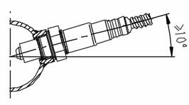
Minimum
mounting angle for the UEGO Sensor
Notes on the Sensor:
You can typically tell if a sensor is starting to fail if it is very slow to respond to changes in A/F, like from blipping the throttle, or slow to show proper signals during warm-up (system power on but engine not running). The response will continue to slow until finally there is no response from the sensor. Running the sensor in "clean" exhaust for a while can partially restore a sensor. See Note below about "cleaning".
-
The sensor contains a ceramic module and should not be subject to mechanical or thermal shock or it may be damaged. Thermal shock would occur if liquid drops of water were to contact the sensor, like if a sampling trap for the DT2-AFR Remote sampler were to over fill.
-
The sensor is not designed for operation on leaded fuels, doing so will shorten sensor life.
-
Long term running in the rich region (Lambda < 0.95) will shorten sensor life, running very rich will dramatically reduce sensor life.
-
High exhaust temperatures (over 850 deg C, 1560 deg F) will shorten sensor life.
-
Engine oil consumption at a rate greater than 1 quart per1,000 miles will shorten sensor life.
-
Do not run the engine with the UEGO sensor installed without power applied to the controller and the sensor plugged in.
It may be possible to "clean" sensors if you run them in a modern, production car with good emissions, with the proper DT2-AF1, DT2-AF2 or DT2-AFG controller connected. This must be done before the sensor has completely failed.
A good rule of thumb for sensor life is: A sensor will last about as long as your spark plugs. If your spark plugs are fouled by lead or very rich running, you sensor is likely to have failed also.
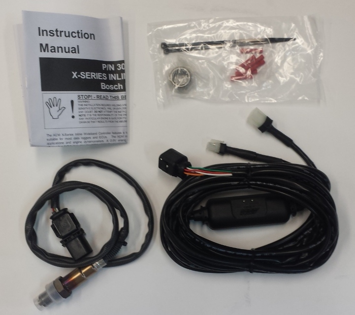
This is a "bare bones"
A/F sensor system. It includes 1 A/F sensor (LSU 4.2 like all our systems)
and the signal conditioning to provide a 0.5 to 4.5 volt signal for a data
logger. The conditioning is molded directly into the cable. This is
our most affordable way to add a single A/F sensor to your data logger, or one
sensor for each cylinder.
click image to enlarge it
The table below lists the features:
|
System |
DT3-AF1 |
| Cost, as of March 2025 | $259, or $299 with AC power supply |
|
Number of Sensors |
1 |
|
Power Required |
1.3 amps |
|
Voltage Required |
9-18 DC * |
|
Serial Data Output (so A/F can be recorded with free software) |
No |
|
0-5 volt Analog Output |
Yes |
|
Linearity of 0-5 volt output |
Linear *** |
| 0-5 Volt Signal Connectors | No, but can be added at additional cost |
|
0-1 volt Output for ECM |
No |
|
Harness and connector temp limit |
220 deg F / 105 deg C |
|
Measurement Range |
.58 to 1.22 lambda (8.5-18 A/F gas) |
| Construction | Very rugged |
* Optional AC power supplies available
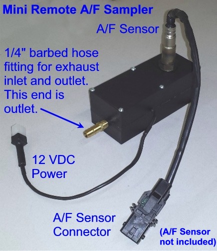
The Mini Remote Sampler provides a pump and sampling cell for mounting the A/F Sensor for easy monitoring of A/F on vehicles on chassis dynos. Simply place your probe in the exhaust pipe and turn on the power and you're done.
The Mini Remote Sampler is also a method that small engine tuners can use to measure A/F on their engines. The A/F sensor is typically too large to be mounted in the exhaust pipe of most single cylinder engines. The remote sampler lets you pull a small sample from the exhaust without affecting the engine's performance.
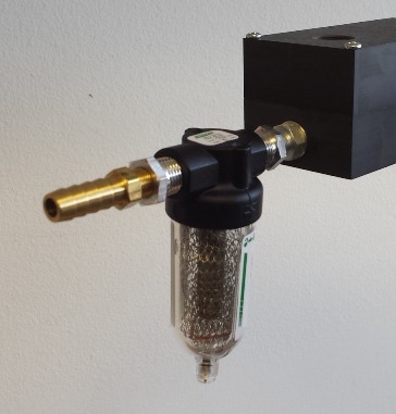 DT2-AFRMT Trap Option **
** Mini Single Remote Sampler Trap (for DT2-AFRM). Provides fittings and low restriction trap for sample before it gets to sensor. Can extend life of sensor "some". To keep the trap low restriction, it must let moisture and some particulate through.
![]() for installation instructions.
for installation instructions.
![]() for an example of one user's installation (with pictures) and experience with
the Mini Remote.
for an example of one user's installation (with pictures) and experience with
the Mini Remote.
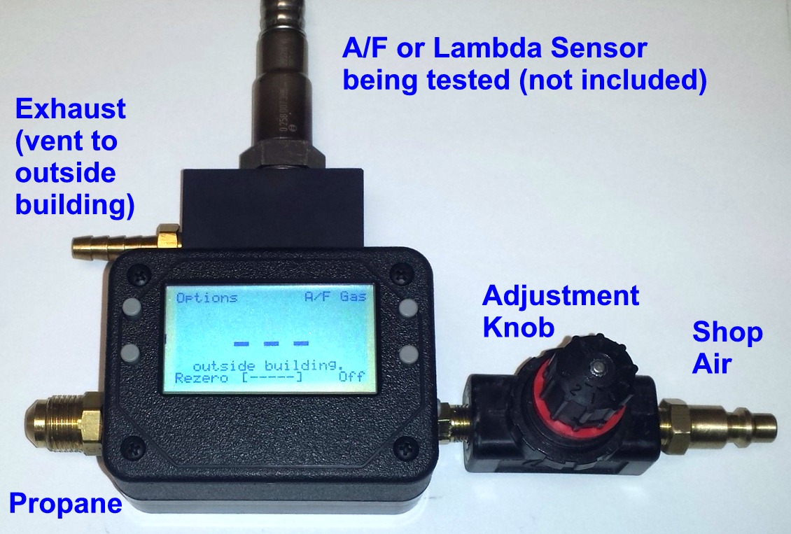
A/F Checker
click image to enlarge ![]() for info on our A/F Checker to verify the accuracy of your A/F
Measurements.
for info on our A/F Checker to verify the accuracy of your A/F
Measurements.
A/F Results
The A/F sensors can even be used on 2 stroke engines, as shown below in the graph of results from an 85 cc 2 stroke. The data was obtained with remote sampler fitted with a special trap for the oil aerosol developed by the dyno operator. The dyno operator says the A/F data is very valuable to track changes in tuning which has a large impact on the 2 strokes power output. Note also how the Head temperature gets warmer as the A/F gets leaner. We will soon be able to fit an aerosol trap to our DT2-AFR Remote Sampling System for 2 stroke engines. (Due to the high oil consumption of 2 strokes, sensor life is reduced and some systems do not recommend use with 2 strokes. We are still investigating the accuracy on 2 strokes and the expected life of the sensors.)

Even Alcohol Briggs & Stratton Kart motors can use the A/F Sensors with proper installation. Below is a graph of 2 tests courtesy of Bryan Pigg of PPE Motorsports in Yazoo City, Mississippi bpigg@terraindustries.com . He mounted his sensor in the muffler (this class required a muffler). The restriction of the muffler better maintained the heat to the sensor, and helped prevent any leakage to allow room air get to the sensor, which makes the sensor read too lean. The graph shows that Test 4 with an A/F in the range of 6.5:1 was too lean for this alcohol motor. When he richened it up to around 5.8:1, he picked up torque and HP throughout the entire RPM range.

![]() to return to the top.
to return to the top.
![]() for
prices.
for
prices.
To Order:
Call 248-473-9230. Visa or Mastercard accepted.